- 您现在的位置:买卖IC网 > Sheet目录1194 > ADT7490ZEVB (ON Semiconductor)BOARD EVALUATION FOR ADT7490
�� �
�
�ADT7490�
�0xFFFF� indicates� that� either� the� fan� has� stalled� or� is� running�
�very� slowly� (<100� RPM).�
�High� Limit� >� Comparison� Performed�
�Because� the� actual� fan� TACH� period� is� being� measured,�
�falling� below� a� fan� TACH� limit� by� 1� sets� the� appropriate�
�status� bit� and� can� be� used� to� generate� an� SMBALERT.�
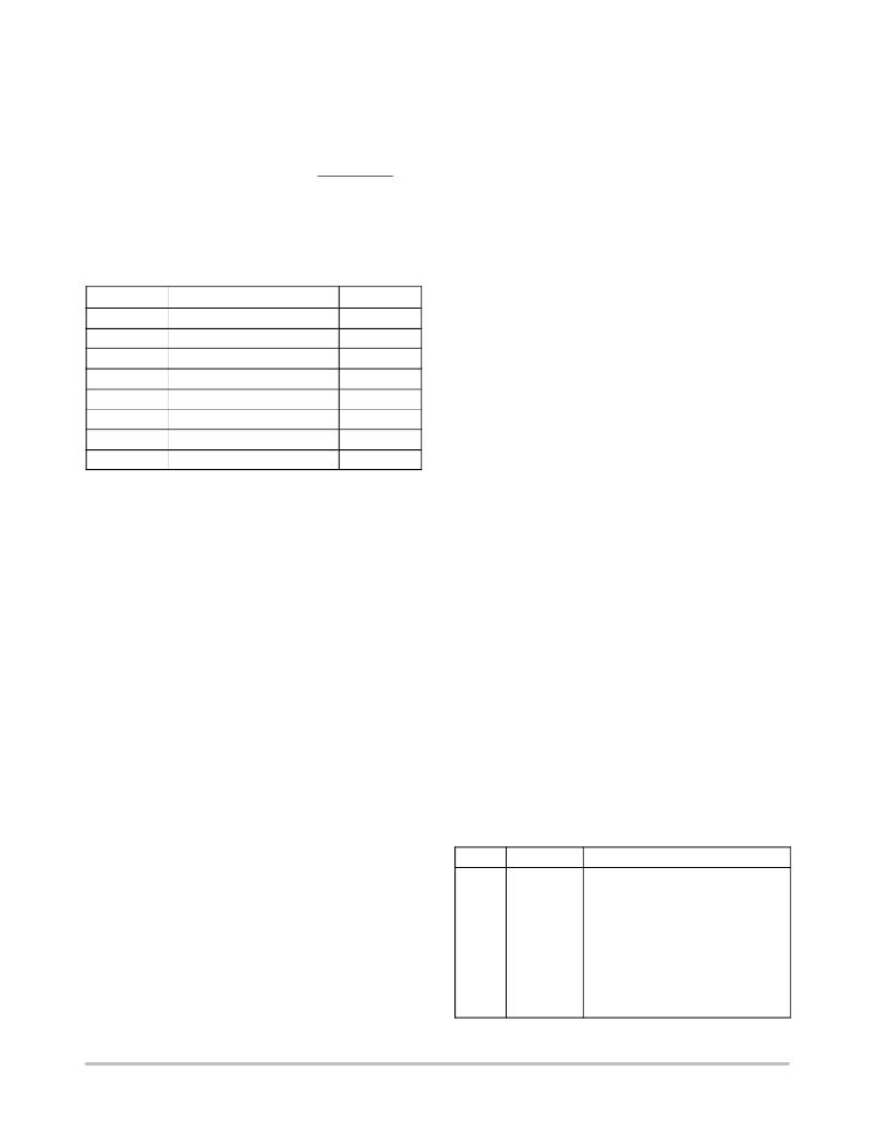
�Fan� TACH� Limit� Registers�
�The� fan� TACH� limit� registers� are� 16-bit� values� consisting�
�of� two� bytes.�
�Table� 31.� FAN� TACH� LIMIT� REGISTERS�
�Fan� Pulses� per� Revolution�
�Different� fan� models� can� output� either� one,� two,� three,� or�
�four� TACH� pulses� per� revolution.� Once� the� number� of� fan�
�TACH� pulses� has� been� determined,� it� can� be� programmed�
�into� the� TACH� pulses� per� revolution� register� (0x7B)� for� each�
�fan.� Alternatively,� this� register� can� be� used� to� determine� the�
�number� or� pulses� per� revolution� output� by� a� given� fan.� By�
�plotting� fan� speed� measurements� at� 100%� speed� with�
�different� pulses� per� revolution� setting,� the� smoothest� graph�
�with� the� lowest� ripple� determines� the� correct� pulses� per�
�revolution� value.�
�TACH� Pulses� per� Revolution� Register�
�Register�
�0x54�
�0x55�
�0x56�
�0x57�
�0x58�
�0x59�
�0x5A�
�0x5B�
�Description�
�TACH1� Minimum� Low� Byte�
�TACH1� Minimum� High� Byte�
�TACH2� Minimum� Low� Byte�
�TACH2� Minimum� High� Byte�
�TACH3� Minimum� Low� Byte�
�TACH3� Minimum� High� Byte�
�TACH4� Minimum� Low� Byte�
�TACH4� Minimum� High� Byte�
�Default�
�0xFF�
�0xFF�
�0xFF�
�0xFF�
�0xFF�
�0xFF�
�0xFF�
�0xFF�
�Bits� [1:0],� FAN1� default� =� 2� pulses� per� revolution�
�Bits� [3:2],� FAN2� default� =� 2� pulses� per� revolution�
�Bits� [5:4],� FAN3� default� =� 2� pulses� per� revolution�
�Bits� [7:6],� FAN4� default� =� 2� pulses� per� revolution�
�00� =� 1� pulse� per� revolution�
�01� =� 2� pulses� per� revolution�
�10� =� 3� pulses� per� revolution�
�11� =� 4� pulses� per� revolution�
�Fan� Spin-up�
�Fan� Speed� Measurement� Rate�
�The� fan� TACH� readings� are� normally� updated� once�
�every� second.�
�When� set,� the� FAST� bit� (Bit� 3)� of� Configuration� Register� 3�
�(0x78),� updates� the� fan� TACH� readings� every� 250� ms.�
�DC� Bits�
�If� any� of� the� fans� are� not� being� driven� by� a� PWM� channel�
�but� are� powered� directly� from� 5.0� V� or� 12� V,� their� associated�
�dc� bit� in� Configuration� Register� 3� should� be� set.� This� allows�
�TACH� readings� to� be� taken� on� a� continuous� basis� for� fans�
�connected� directly� to� a� dc� source.� For� 4-wire� fans,� once� high�
�frequency� mode� is� enabled,� the� dc� bits� do� not� need� to� be� set�
�because� this� is� automatically� done� internally.�
�Calculating� Fan� Speed�
�Assuming� a� fan� with� a� two� pulses� per� revolution,� and� with�
�the� ADT7490� programmed� to� measure� two� pulses� per�
�revolution,� fan� speed� is� calculated� by�
�Fan� Speed� (RPM)� =� (90,000� ?� 60)/Fan� TACH� Reading�
�where� Fan� TACH� Reading� is� the� 16-bit� fan� tachometer�
�The� ADT7490� has� a� unique� fan� spin-up� function.� It� spins�
�the� fan� at� 100%� PWM� duty� cycle� until� two� TACH� pulses� are�
�detected� on� the� TACH� input.� When� two� TACH� pulses� have�
�been� detected,� the� PWM� duty� cycle� goes� to� the� expected�
�running� value,� for� example,� 33%.� The� advantage� of� this� is�
�that� fans� have� different� spin-up� characteristics� and� take�
�different� times� to� overcome� inertia.� The� ADT7490� runs� the�
�fans� just� fast� enough� to� overcome� inertia� and� is� quieter� on�
�spin-up� than� fans� programmed� to� spin� up� for� a� given� spin-up�
�time.�
�Fan� Startup� Timeout�
�To� prevent� the� generation� of� false� interrupts� as� a� fan� spins�
�up,� because� the� fan� is� below� running� speed,� the� ADT7490�
�includes� a� fan� startup� timeout� function.� During� this� time,� the�
�ADT7490� looks� for� two� TACH� pulses.� If� two� TACH� pulses�
�are� not� detected,� an� interrupt� is� generated.�
�Fan� startup� timeout� can� be� disabled� by� setting� Bit� 3�
�(FSPDIS)� of� Configuration� Register� 7� (0x11).�
�Table� 32.� PWM1,� PWM2,� PWM3� CONFIGURATION�
�(REG.� 0x5C,� REG.� 0x5D,� REG.� 0x5E)�
�reading.�
�Example�
�TACH1� High� Byte� (Register� 0x29)� =� 0x17�
�TACH1� Low� Byte� (Register� 0x28)� =� 0xFF�
�What� is� Fan� 1� speed� in� RPM?�
�Fan� 1� TACH� Reading� =� 0x17FF� =� 6143� (decimal)�
�RPM� =� (f� ?� 60)/Fan� 1� TACH� Reading�
�RPM� =� (90,000� ?� 60)/6143�
�Fan� Speed� =� 879� RPM�
�Bit�
�[2:0]�
�Mnemonic�
�SPIN�
�Description�
�These� Bits� Control� the� Startup�
�Timeout� for� PWM1� (0x5C),�
�PWM2� (0x5D),� PWM3� (0x5E).�
�000� =� No� Startup� Timeout�
�001� =� 100� ms�
�010� =� 250� ms� (Default)�
�011� =� 400� ms�
�100� =� 667� ms�
�101� =� 1� s�
�110� =� 2� s�
�111� =� 4� s�
�http://onsemi.com�
�31�
�发布紧急采购,3分钟左右您将得到回复。
相关PDF资料
ADZS-21262-1-EZEXT
BOARD DAUGHTER FOR ADSP-21262
ADZS-BF-EZEXT-1
BOARD DAUGHTER ADSP-BF533/561KIT
ADZS-BFAV-EZEXT
BOARD DAUGHT ADSP-BF533,37,61KIT
ADZS-BFSHUSB-EZEXT
BOARD DAUGHTER EZ EXTENDER
ADZS-BRKOUT-EX3
ADZS-BRKOUT-EX3
ADZS-SHAUDIO-EZEXT
SHARC AUDIO EZ-EXTENDER
ADZS-WVGALCD-EX3
BOARD EXTENDER WVGA/LCD EI3
AGA-3
FUSE 3A 125VAC 1AG FAST
相关代理商/技术参数
ADT75
制造商:AD 制造商全称:Analog Devices 功能描述:+-1∑C Accurate, 12-Bit Digital Temperature Sensor
ADT7516
制造商:AD 制造商全称:Analog Devices 功能描述:SPI/I2C Compatible, Temperature Sensor, Four Channel ADC and Quad Voltage Output DAC
ADT7516_06
制造商:AD 制造商全称:Analog Devices 功能描述:SPI-/I2C-Compatible, Temperature Sensor,4-Channel ADC and Quad Voltage Output
ADT7516ARQ
功能描述:IC TEMP SNSR QUAD DAC 16-QSOP RoHS:否 类别:集成电路 (IC) >> PMIC - 热管理 系列:- 标准包装:2,500 系列:SilentSense™ 功能:温度监控系统(传感器) 传感器类型:内部和外部 感应温度:-55°C ~ 125°C,外部传感器 精确度:±2°C 本地(最大),±3°C 远程(最大) 拓扑:ADC(三角积分型),比较器,寄存器库 输出类型:I²C?/SMBus? 输出警报:是 输出风扇:是 电源电压:2.7 V ~ 5.5 V 工作温度:-55°C ~ 125°C 安装类型:表面贴装 封装/外壳:8-TSSOP,8-MSOP(0.118",3.00mm 宽) 供应商设备封装:8-MSOP 包装:带卷 (TR) 其它名称:MIC284-2BMMTRMIC284-2BMMTR-ND
ADT7516ARQ-REEL
制造商:Analog Devices 功能描述:Temp Sensor Digital Serial (4-Wire, SPI, I2C) 16-Pin QSOP T/R 制造商:Analog Devices 功能描述:TEMP SENSOR DGTL SERL (4-WIRE, SPI) 16QSOP - Tape and Reel
ADT7516ARQ-REEL7
制造商:Analog Devices 功能描述:Temp Sensor Digital Serial (4-Wire, SPI, I2C) 16-Pin QSOP T/R 制造商:Analog Devices 功能描述:TEMP SENSOR DGTL SERL (4-WIRE, SPI) 16QSOP - Tape and Reel
ADT7516ARQZ
功能描述:IC TEMP SNSR QUAD DAC 16-QSOP RoHS:是 类别:集成电路 (IC) >> PMIC - 热管理 系列:- 标准包装:3,000 系列:- 功能:温度开关 传感器类型:内部 感应温度:85°C 分界点 精确度:±6°C(最小值) 拓扑:ADC(三角积分型),比较器,寄存器库 输出类型:开路漏极 输出警报:是 输出风扇:是 电源电压:2.7 V ~ 5.5 V 工作温度:-55°C ~ 125°C 安装类型:表面贴装 封装/外壳:SC-74A,SOT-753 供应商设备封装:SOT-23-5 包装:带卷 (TR) 其它名称:ADT6501SRJZP085RL7-ND
ADT7516ARQZ-REEL
制造商:Analog Devices 功能描述:Temp Sensor Digital Serial (4-Wire, SPI, I2C) 16-Pin QSOP T/R